Showing posts with label bolting. Show all posts

Monday, 28 October 2024

How to Choose a Hydraulic Torque Wrench


 Hydraulic torque wrenches are the heavy hitters in the bolting world, delivering immense torque for tackling the most demanding industrial applications. From wind turbine construction to pipeline assembly, these powerful tools ensure the precise and secure fastening of critical joints. But with a vast array of options available, selecting the right hydraulic torque wrench for your needs can feel overwhelming. Worry not, for this comprehensive guide will equip you with the knowledge to make an informed decision.

Understanding Hydraulic Torque Wrenches:

Unlike their manual counterparts, hydraulic torque wrenches utilize pressurized fluid to generate the necessary force for tightening or loosening bolts. This translates to significantly higher torque output compared to manual wrenches, making them ideal for large, high-strength bolts.

Here are some key components of a hydraulic torque wrench system:

  • Hydraulic Power Unit: This acts as the heart of the system, generating the pressurized fluid used by the wrench. Power units can be electric, engine-powered, or hand-operated depending on your needs.
  • Hydraulic Hose: This flexible line transmits the pressurized fluid from the power unit to the wrench.
  • Hydraulic Torque Wrench: This is the workhorse, responsible for converting the hydraulic pressure into torque to tighten or loosen the bolt.

Factors to Consider When Choosing a Hydraulic Torque Wrench:

Now, let's delve into the critical factors that will influence your choice of hydraulic torque wrench:

  • Torque Requirement: This is the most crucial consideration. Identify the maximum torque needed for the specific application. Consulting your project specifications or fastener manufacturer's recommendations is essential to determine the required torque range.
  • Application: Different applications have unique demands. Consider factors like access limitations, required speed, and portability. For example, wind turbine maintenance often requires low-profile wrenches for confined spaces.
  • Frequency of Use: If you'll be using the wrench frequently, consider investing in a more durable model built for high-volume usage.
  • Hydraulic Compatibility: Ensure the wrench and power unit operate at compatible pressure ranges.
  • Accuracy Requirements: Hydraulic torque wrenches typically offer high accuracy, but some applications might demand even stricter precision. Look for wrenches with certified accuracy levels to meet your needs.
  • Safety Features: Hydraulic wrenches involve pressurized systems. Opt for models with overload protection and pressure release valves for enhanced safety.
  • Accessories: Hydraulic wrenches often require additional accessories like cassettes (drive heads for different size bolts), reaction arms (to counter the torque reaction), and calibration equipment. Consider the availability and cost of these necessary add-ons.
  • Budget: Hydraulic torque wrenches can range significantly in price depending on their capabilities and features. Determine your budget beforehand to narrow down your options.

Beyond the Basics: Key Features to Explore:

  • Cassette Drive: Hydraulic wrenches utilize cassettes to accommodate various bolt sizes. Choose a system that offers a wide range of cassettes to handle diverse applications.
  • Single vs. Double Acting: Single-acting wrenches apply torque only in one direction, while double-acting wrenches can both tighten and loosen bolts. Consider the versatility of a double-acting wrench if your application requires both tightening and loosening operations.
  • Digital Readouts: Modern wrenches often come equipped with digital readouts for real-time torque monitoring, enhancing accuracy and control.
  • Data Logging Capabilities: Advanced models can even record and store torque data for documentation and quality control purposes.

Investing in the Right Tool:

A hydraulic torque wrench is a valuable investment, ensuring the safe and precise completion of critical bolting tasks. By carefully considering the factors outlined above and exploring the available options, you can select the ideal wrench for your specific needs. Remember, a qualified hydraulic tool supplier can provide valuable guidance and assist in choosing the perfect tool for your application.

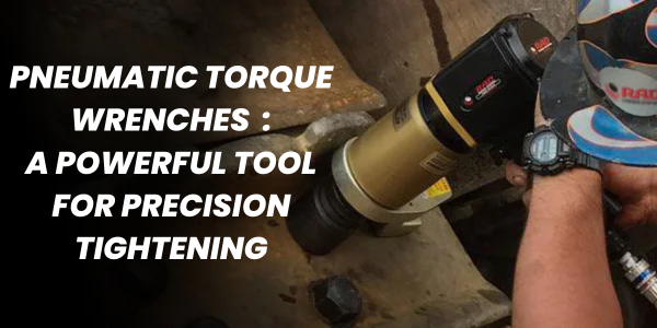
Pneumatic Torque Wrenches: A Powerful Tool for Precision Tightening


Pneumatic torque wrenches are essential tools in industries where precise and efficient tightening of bolts is critical. These wrenches utilize compressed air as their power source, providing a reliable and adjustable means of applying torque to bolts.

How Pneumatic Torque Wrenches Work

A pneumatic torque wrench consists of a pneumatic motor, a gear reduction system, and a torque reaction mechanism. When compressed air is supplied to the motor, it rotates a gear train that drives a reaction arm. The reaction arm is connected to a torque sensor, which measures the force exerted on the bolt. Once the desired torque setting is reached, the wrench automatically shuts off, preventing over-tightening.

Key Advantages of Pneumatic Torque Wrenches

  • High Power Output: Pneumatic torque wrenches can deliver significant torque, making them suitable for heavy-duty applications.
  • Versatility: They can be used in various industries, including automotive, aerospace, manufacturing, and construction.
  • Precision: With proper calibration, pneumatic torque wrenches can achieve high levels of accuracy in torque application.
  • Efficiency: They are fast and efficient, reducing assembly time and improving productivity.
  • Durability: Pneumatic wrenches are generally durable and reliable, with long service life.

Applications of Pneumatic Torque Wrenches

  • Automotive Assembly: Tightening wheel nuts, engine bolts, and other critical components.
  • Aerospace Manufacturing: Assembling aircraft structures and components.
  • Industrial Machinery: Installing and maintaining machinery components.
  • Construction: Securing structural components and equipment.

Choosing the Right Pneumatic Torque Wrench

When selecting a pneumatic torque wrench, consider the following factors:

  • Torque Range: Choose a wrench with a torque range that suits your specific applications.
  • Accuracy: Ensure the wrench has the required accuracy level for your tasks.
  • Air Consumption: Consider the air consumption rate to determine if your air compressor can provide sufficient supply.
  • Ergonomics: Choose a wrench with a comfortable grip and ergonomic design for operator comfort.

Safety Considerations

  • Proper Training: Operators should be trained in the safe and proper use of pneumatic torque wrenches.
  • Regular Maintenance: Regular maintenance, including lubrication and calibration, is essential for optimal performance and safety.
  • Safety Equipment: Wear appropriate safety equipment, such as safety glasses and gloves, when using pneumatic torque wrenches.

Pneumatic torque wrenches are indispensable tools for industries that require precise and efficient bolt tightening. By understanding their operation, advantages, and applications, you can select the right wrench for your specific needs and ensure safe and reliable performance.

Design and Analysis of a Hydraulic Bolt Tensioner


 Introduction

Hydraulic bolt tensioners are essential tools in various industries, from construction to manufacturing. They offer a precise and efficient way to apply controlled tension to bolts, ensuring structural integrity and preventing premature failure. This blog will delve into the key design considerations and analytical techniques involved in creating a reliable and effective hydraulic bolt tensioner.

Design Considerations

  1. Bolt Size and Material: The tensioner must be compatible with the specific bolt size and material. Factors such as bolt diameter, thread pitch, and yield strength influence the required tensioning force.
  1. Hydraulic Pressure: The maximum operating pressure of the hydraulic system determines the achievable tensioning force. Higher pressure can provide greater tension, but it's essential to ensure the system's safety and reliability.
  1. Tensioning Mechanism: The choice of tensioning mechanism depends on the application and desired level of accuracy. Common options include hydraulic cylinders, hydraulic rams, and hydraulic jacks.
  1. Safety Features: Safety is paramount in hydraulic bolt tensioners. Features like pressure relief valves, safety locks, and clear operating instructions are crucial to prevent accidents.
  1. Portability and Maneuverability: For field applications, portability is essential. The tensioner should be designed for easy transportation and operation in various environments.

Analytical Techniques

  1. Force Analysis: To determine the required hydraulic pressure, a force analysis is conducted. This involves calculating the tension force needed to achieve the desired bolt preload and considering factors like friction and mechanical efficiency.
  1. Stress Analysis: Finite element analysis (FEA) is commonly used to assess the stress distribution in the tensioner components. This helps identify potential weak points and ensure the design can withstand the applied loads.
  1. Hydraulic System Analysis: The hydraulic system's performance is analyzed to ensure it can deliver the required pressure and flow rate. Factors like fluid viscosity, pipe size, and pump capacity are considered.
  1. Fatigue Analysis: If the tensioner is subjected to cyclic loading, a fatigue analysis is performed to assess its durability and prevent failure due to repeated stress.

Case Study: Designing a Tensioner for a Bridge Construction Project

Consider a project requiring the installation of large-diameter bolts to secure bridge beams. The design process would involve:

  • Bolt Specification: Determining the bolt size, material, and required preload based on structural calculations.
  • Hydraulic System Design: Selecting a suitable hydraulic pump and cylinder to provide the necessary tensioning force.
  • FEA Analysis: Modeling the tensioner and bridge components to evaluate stress distribution and identify critical areas.
  • Safety Features: Incorporating safety features like pressure relief valves and emergency stop mechanisms.
  • Testing and Validation: Conducting static and dynamic tests to verify the tensioner's performance and safety.

Conclusion

Designing and analyzing a hydraulic bolt tensioner requires a comprehensive understanding of mechanical engineering principles, hydraulic systems, and materials science. By carefully considering design factors and employing analytical techniques, engineers can create reliable and efficient tools that meet the specific needs of various industries.


Thursday, 21 July 2016

Bolting Solution for EPC & Construction Industry

EPC stands for Engineering, Procurement, Construction and is a prominent form of contracting agreement in the construction industry.The engineering and construction contractor will carry out the detailed engineering design of the project, procure all the equipment and materials necessary, construct to deliver a functioning facility or asset,to commission and handover of the project to the End-User
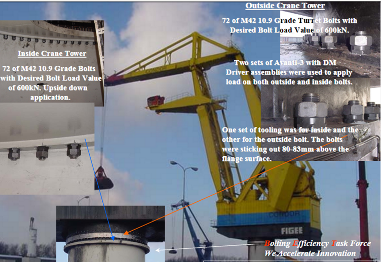
While executing the various aspects of projects,a perfect bolting is mandatory. Bolting is required in various applications like Crane foundation Bolt ,Crane Joint Integrity ,Tower Crane ,Surge Vessels ,Deck Cranes, Crane Turret Bolts ,Planetary Drive Gear and many more.

ABS Bolting solution for various application are as following-

1.Application Name- Tower Crane Application
     Tool Name-Avanti-8 with Reaction Fixture


2.Application Name- Crane Foundation Bolt
   Tool Name-Stealth 8 Square Drive Hydraulic Torque Wrench


3. Application Name- Crane Joint Inegrity
     Tool Name- Avanti-3 Square Drive Hydraulic Torque Wrench.


4.Application Name- Surge Vessels
       Tool Name- JGun Duol Speed Pneumatic Torque Wrench


5.Application Name- Desk Cranes
      Tool Name - Avanti Square Drive Hydraulic Torque Wrench


6.Application Name- Planetary Drive Gear Solution
      Tool Name- JGun Duol Speed Pneumatic Torque Wrench


7.Application Name- Crane Turret Bolts 
      Tool Name- Avanti Square Drive Hydraulic Torque Wrench


Tuesday, 19 January 2016

Lithium Gun-Operation & Application

The Lithium Series dual speed torque gun provides the speed and convenience of a pneumatic torque gun without the noise, vibration and load variation.The Lithium Gun is a precision torque/tension compatible machine that you can set and get your desired load.


 The Lithium Gun uses precision gearing to produce constant, calibrated power assuring that you will achieve bolt load within your window of accuracy every time.It give Bolt Load Accuracy Within ±5%.The Lithium Gun is a precision torque/tension compatible machine that you can set and get your desired load. 


The Lithium Gun uses precision gearing to produce constant, calibrated power assuring that you will achieve bolt load within your window of accuracy every time.It is Lightweight, Durable & Powerful and have High Speed Rundown,


 Final Torque and Angle Capabilities.The highest power-to-weight ratio of any battery powered torque gun. High quality components ensure superior performance and durability. Its aluminum frame makes it lightweight yet resistant to damage.

Operations-

Each LithiumTorque Gun is supplied completely assembled and ready for use.
A full kit contains:

• Lithium Torque Gun
• Two 36V Li-ion 3.9Ah Battery Packs
• 36V Battery Charger
• Battery Charger Power Supply
• Reaction Arm


SETUP

Two Speed Operation
Each Lithium torque gun is equipped with a two speed gearbox.The gearbox has two modes:
• RUNDOWN MODE: Used to run nuts down to seated position ready to torque.
• TORQUE MODE: Used for final torqueing in TORQUE ONLY and TORQUE AND ANGLE sub-modes.To switch between RUNDOWN and TORQUE settings, flip the gear select switch located underneath the front aluminium bearing housing. In the rare event the gear selector doesn’t engage, a very brief pulse from the trigger is all that is needed to allow gear engagement.


Battery Pack Installation and Removal
To install the battery pack into the tool handle, align the base of the tool with the rails in the tool handle and slide the battery pack firmly into the handle until you hear the lock snap in to place. To remove the battery pack from the tool, press the release button (as shown above) and firmly pull the battery pack out of the tool handle.

Charging Procedure
1. Plug the charger power supply into the charger cradle using the three pin plug, then tighten the retaining collar on the plug.
2. Plug the charger power supply into an appropriate outlet before inserting a battery pack.
3. Insert the battery pack into the charger cradle. The charger is equipped with a two light charge.Indicator that will be either red or green according to the state of charge of the battery pack.
4. The completion of the charge is indicated by a green light which also indicates an idle state. The pack is fully charged and may be used at this time or left on the charger.
LED Indicators:
• No Battery – Flashing Red Light
• Charging – Solid Red Light
• Fully Charged – Solid Green Light
• Short Circuit – Flashing Red Light
• Reverse Polarity – Flashing Red Light
• Damaged Battery – Flashing Red Light


Power
The LITHIUM gun battery charger can operate at 110V or 220V AC. The plug is configured for North American outlets so other regions may require adapters.

Reaction Arm.
Each electric torque gun is equipped with a universal reaction arm. The reaction arm is used to absorb and counteract any opposing forces created by the operation of the torque gun. Use the appropriately sized reaction arm or HYTORC Washer based on your application.


Basic Operation


Upon power up, the LITHIUM gun will initialize and show the main display screen as shown in Figure 12. At start up the LITHIUM gun is ready to operate at the initial or the last Torque, Angle and Release angle settings. If these settings are correct and when ready to tighten a fastener, place the gun on the application and pull the trigger, the display will then ask the operators to “Press any Button to Continue”. This step is to ensure the operator removes his second hand from the path of the reaction arm. While continuing to hold the trigger the opposite hand should press any button on the display to start the tightening process. Continue to hold the trigger until the gun comes to a complete stop. 

While torqueing, the AMBER LED will light up showing BUSY. When done, the torque gun will beep once and the GREEN LED will turn ON. In case of error, the torque gun will beep 4 times and the RED LED will be ON. If failed, an error message will be shown on the display screen. If Release angle is set, the gun will automatically run backwards to the specified angle to release windup from reaction torque. To change or set torque, angle and release angle see “Setting Torque and Angle” section. To loosen, press the center button. The torque setting will be automatically set to the maximum allowed torque for the particular type of gun, i.e. for BTM-1000 Series LITHIUM guns, the MAX Torque is approximately 1200 ft. lbs. Press and hold the power trigger switch while the socket turns and loosens the nut. In reverse direction, the torque gun is set to maximum torque in order to loosen the nut. Use extreme caution when running in this mode.

Basic Function Descriptions
Torque: Allows the operator to enter the target torque that the gun will seek when the trigger is pulled and held.
Angle: If an angle setting is above “0” the gun will add this angle of rotation to a completed torque operation using the maximum output of the unit.
Release Angle: After completing an operation, the gun will automatically run backwards the specified angle to release windup from reaction torque.


Setting Torque and Angle


To Set the Torque and Angle: 
Press and hold center key with right facing arrow to toggle from screens for setting Torque, Angle and Release Angle. While on screen, use up and down arrows keys to select value.


Note: Set the Angle to 0, if working only in Torque Mode. The LITHIUM gun is ready to operate once the desired Torque setting is entered. There is no need to toggle through Angle and Release angle screens if they are already set to 0.

TORQUE GUN OPERATION

Tightening
1. Make sure the torque gun and the reaction arm are in position for tightening.
2. Ensure the reaction arm is squarely against a solid reaction point.
3. Pull the power trigger switch, the press any button with your opposite hand.
4. When specified torque is reached, the LITHIUM gun will BEEP once and the Green LED will turn ON.
5. If Release angle is set, the gun will automatically run backwards the specified angle to release windup from reaction torque.
6. If the LITHIUM gun fails to set the torque properly, it will BEEP 4 times and the Red LED will turn ON while also showing the error on the display. In case of error, try again by repeating process from Step 3. If error continues, STOP and check for any abnormalities with the LITHIUM gun or the nut/bolt being tightened.
7. Release the power trigger switch.
8. If the trigger is released prematurely, the display will show an error and the Red LED will be ON. In this case, restart tightening process from step 3.
9. The nut is now tight at the current torque setting. Proceed to the next nut.


Tightening with Angle
1. Follow the steps in Tightening above from 1 to 3.
2. When preset torque is reached, the LITHIUM gun will turn the nut in degrees set by the Angle.
3. When the specified angle is set, the gun will BEEP once and the Green LED will turn ON.
4. Proceed and follow steps 5 to 9 in Tightening above.

Loosening
1. Set the direction to loosen by pressing the middle button. The torque setting will be automatically set to the maximum allowed torque for the particular type of gun, i.e. for BTM-1000 Series LITHIUM guns, the MAX Torque is approximately 1200 ft. lbs.
2. Make sure the torque gun and the reaction arm are in position for loosening.
3. Make sure the reaction arm is squarely against a solid reaction point.
4. Press and hold the power trigger with one hand. Then, when prompted, press any button with the other hand to start.
5. Release the power trigger switch when the nut is loose enough to be removed by hand.

Application-


It is ideal for Infrastructure and Power Generation Industry.


Tuesday, 12 January 2016

Electric Torque Wrench- Operation & Specification


An electric torque wrench is a gearbox that is connected to an electric motor. This gearbox is designed in such a way that it absorbs the torque, allowing the user to operate the wrench with minimal effort. These are typically used when there is no need for torque strength accuracy being used on the nut or bolt, or when a very stubborn nut needs to be removed.
 The gearboxes can be of ratios of up to 4000:1. and this is adjusted by controlling the voltage. Due to the fact it is powered by electricity, you can find waterproof models for when water is a concern on the jobsite. It is often confused with an impact wrench due to its similar design, but it is in fact a totally different tool, and is even more different from a hydraulic torque wrench. It all comes down to the job and getting the right tool for it.


Operation  of Electric Torque Wrench 

General

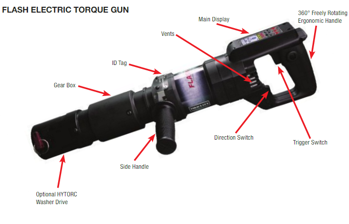
Each electric torque gun is supplied completely assembled and ready for use.  A side handle is supplied for better hold and grip during operation.

Setup


Reaction Arm
Each electric torque gun is equipped with a universal reaction arm.  The reaction arm is used to absorb and counteract any opposing forces created by the operation of the torque gun. Use the appropriate size reaction arm or HYTORC Washer based on your application.
Power
The FLASH GUN can operate at 110V or 220V AC based on the model configuration. Ensure proper voltage is present at the power outlet and insert the power chord into the nearest 110V (black cord) or 220V (yellow cord) outlet. Upon power up, the FLASH GUN will initialize and show the main display screen.


Basic Operation

At Start up the FLASH GUN is ready to operate at the initial or the last Torque, Angle and Release Angle settings. If these settings are correct and when ready to tighten a fastener, place the gun on the application and press the trigger until the reaction arm firmly makes contact with the reaction point. Press and hold the trigger until the gun comes to a complete stop.
While torquing, the YELLOW LED will light up showing BUSY. When done, the torque gun will beep once and the GREEN LED will turn ON. In case of error, the torque gun will beep 4 times and the RED LED will be ON. If failed, an error message will be shown on the display screen. If Release angle is set,     the gun will automatically run backwards to the specified angle to release windup from reaction torque.

To change or set Torque, Angle and Release Angle see the “Setting Torque and Angle” section.
To loosen, set the direction switch to ‘L’. See figure 11 for direction switch operation. The torque setting will be automatically set to the maximum allowed
torque for the particular type of gun, i.e. for FG3 Series FLASH-3 GUNS, the max torque is 3150 ft. lbs. Press and hold the power trigger switch while the socket turns and loosens the nut. In reverse direction, the torque gun is set to maximum torque in order to loosen the nut. Use extreme caution when running in this mode. The FLASH GUN can operate on both left hand and right hand threads. See the “Additional Options” section for changing to/from left hand or right hand thread modes.


Basic Function Descriptions

Torque:  Allows the operator to enter the target torque that the gun will seek when the trigger is pulled and held.  
Angle:  If an angle setting is above “0” the gun will add this angle of rotation to a completed torque operation using the maximum output of the unit. If the FLASH GUN reaches its maximum torque before completing the angle then it will stop with an error: “Angle Failure: Out of Torque Range”
Release Angle:  After completing an operation, the gun will automatically run backwards to the specified angle to release windup from reaction torque.
Direction Switch
1. (R) Tighten 2. (L) Loosen


Setting Torque and Angle

The main screen shows three settings for Torque, Angle and Release Angle. The three settings are toggled with the left most soft button. Increase and decrease each value by using the center and right-most soft buttons.
Follow these steps to set the torque and angle:
1. Set the direction switch to ‘R’ to tighten. See figure 11 for directional switch. 2. Set the desired torque by pressing the soft push buttons corresponding to the up/down arrow key indicators. When desired torque is displayed, press the left-most soft button corresponding
to the “Right Arrow” to go to the next screen for setting the angle. 3. Set the desired angle by pressing the soft buttons corresponding to the up/down arrow key indicators. When desired angle is displayed, press left-most soft button corresponding to the “Right Arrow” to go to the next screen for setting the release angle. 4. Set the desired release angle by pressing the soft buttons corresponding to the up/down arrow key indicators. When desired release angle is displayed, press left-most soft button corresponding to the “Right Arrow” to go back to main screen with the torque setting.


TORQUE GUN OPERATION


Tightening


1. Set the direction switch to ‘R’ to tighten. See figure 11 for directional switch. 2. Set the desired torque value as described in “Setting Torque and Angle” section. 3. Make sure the torque gun and the reaction arm are in position for tightening. 4. Ensure the reaction arm is squarely against a solid reaction point. 5. Press and hold the power trigger switch while the socket turns. 6. When specified torque is reached, the FLASH GUN will stop, BEEP once and the Green LED
will turn ON.
7. If Release angle is set, the gun will automatically run backwards to the specified angle to release windup from reaction torque.
8. If the FLASH GUN fails to set the torque properly, it will BEEP 4 times and the Red LED turn ON while also showing the error on the display. In case of error, try again by repeating process from Step 3. If error continues, STOP and check for any abnormalities with the FLASH GUN or the nut/bolt being tightened.
9. Release the power trigger switch.
10. If the trigger is released prematurely, the display will show an error and the Red LED will turn ON. In this case, restart tightening process from step 3.
11. The nut is now tight at the current torque setting. Proceed to the next nut.


Tightening with Angle


1. Set the direction switch to ‘R’ to tighten. See figure 11 for directional switch. 2. Set the desired pre-torque and angle values as described in the “Setting Torque and Angle”
section. 3. Follow the steps 3 to 5 for Tightening above. 4. When preset torque is reached, the FLASH GUN will turn the nut in degrees set by the angle. 5. When the specified angle is set, the gun will stop, BEEP once and the Green LED will turn ON. 

Memory Options


By pressing the left-most button and holding it, the memory menu will be displayed. Figure 13 shows the memory options menu. On this menu, you can save the current settings, or load previously stored settings.
There are 8 memory locations for saving and loading both torque and angle settings. Use the up and down arrow keys to choose from the highlighted numbered memory locations. 
Press the left-most button to select the current memory location. Press the corresponding down arrow key button to save the current settings to the selected memory location. To load the contents of the memory location, press the corresponding up arrow key button. To return to main menu without saving/loading, press the left-most button.

Application


It is ideal for Infrastructure and Power generation Industries.